Internal Interface
DIP Switch
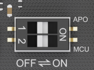
The DIP switch on the LattePanda Iota allows you to customize the behavior for Auto Power-On and MCU Power Control. Below is a detailed breakdown of each setting:
| Actuator Label | Function | Position | Behavior |
|---|---|---|---|
| APO | Auto Power-On | OFF (Default) | System requires manual press of the power button to boot after power is connected. |
| ON | System automatically powers on as soon as external power is applied — ideal for headless or embedded deployments. | ||
| MCU | MCU Power Control | OFF (Default) | Onboard MCU remains inactive until the system is powered on via the power button. |
| ON | Onboard MCU stays active immediately upon power connection(before OS boot). Useful for pre-boot sensor control or automation. |
Note
Once Auto Power-On is set to ON, LattePanda board will automatically power on when it receives power, regardless of the RTC battery.
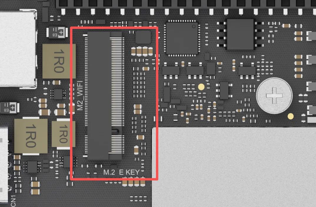
M.2 E Key Slot
LattePanda Iota features one M.2 E Key slot for modern wireless modules, enabling high-speed Wi-Fi and Bluetooth connectivity.
Key Specifications
- Slot Type: M.2 E Key
- Available Lanes: PCIe 3.0 x1, USB 2.0, CNVio2
- Compatible Module Size: 2230
Compatible Device
This slot is primarily intended for Wi-Fi and Bluetooth combo cards. However, it can also accommodate other M.2 E Key devices that utilize the available PCIe interface, such as M.2 to SATA adapters.
- Wireless Modules: M.2 2230 form factor with either PCIe or CNVio2 lane.
- Other Devices: M.2 E Key peripherals compatible with the 2230 size and PCIe lane.
Tested Modules
To ensure stability and performance, we have tested and confirmed compatibility with the following popular wireless modules:
- Intel AC8265 WiFi 5
- Intel AX210 WiFi 6E
- Intel BE200 WiFi 7
- Intel AX211
- Intel AX200
- Intel AX201
Note
- Antenna Connection: M.2 wireless modules require external antennas to function correctly. Remember to connect two antennas to the IPEX4 connectors on the module before use.
- Driver Installation: After installing the hardware, you will need to install the appropriate drivers for your operating system. These can typically be downloaded directly from the module manufacturer's website (e.g., Intel's official support page).
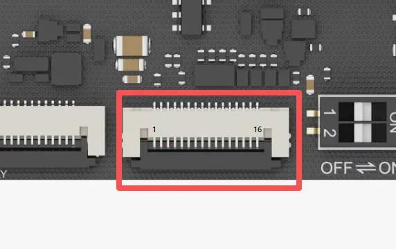
PCIe 3.0 x1 FPC Connector
The LattePanda Iota is equipped with a versatile PCIe 3.0 x1 FPC (Flexible Printed Circuit) expansion connector. By adopting the same pinout as the Raspberry Pi 5's PCIe connector, it allows you to tap into a growing ecosystem of expansion boards.
This connector exposes a native PCIe 3.0 x1 lane, delivering up to 8 GT/s of bandwidth, perfect for data-intensive applications.
Key Specifications
- Connector Type: 16-pin FPC, 0.5mm Pitch
- Available Lane: PCIe 3.0 x1
Pinout Definition
| Pin | Signal Name | Description |
|---|---|---|
| 1 | 5V | 5V Power Output |
| 2 | 5V | 5V Power Output |
| 3 | GND | Ground |
| 4 | PCIE_CLK_P | Reference Clock, Positive |
| 5 | PCIE_CLK_N | Reference Clock, Negative |
| 6 | GND | Ground |
| 7 | PCIE_RX_P | PCIe Receive Lane 0, Positive |
| 8 | PCIE_RX_N | PCIe Receive Lane 0, Negative |
| 9 | GND | Ground |
| 10 | PCIE_TX_P | PCIe Transmit Lane 0, Positive |
| 11 | PCIE_TX_N | PCIe Transmit Lane 0, Negative |
| 12 | GND | Ground |
| 13 | PCIE_PWR_EN | High Level(3.3V) Output to enable PMIC on exp. board or HAT. When OS is running or sleeping, this pin will output HIGH. |
| 14 | PCIE_DET_WAKE | Wake-up Signal, Active Low Pull this pin LOW to wake the LattePanda board from sleep state. |
| 15 | PCIE_CLKREQ_N | Reference Clock Request, Active Low |
| 16 | PCIE_RST | PCIe Device Reset, Active Low |
Compatible Exp. Board
- M.2 M-Key Expansion Board (for NVMe SSDs or AI Accelerator Card)
- PoE Expansion Board (Power over Ethernet for network connectivity)
- Most PCIe expansion boards or HATs for Raspberry Pi 4 or 5
5V Power Output
- The 5V power output has two pins and shares a maximum current of 2.2 A.
- The BIOS default power control is: enable the 5V power output when the OS is running or sleeping; disable the 5V power output when the OS is not running, such as during shutdown or hibernation.
Note
- FPC Cable Required: To connect an expansion board, you will need a compatible 16-pin FPC cable designed for PCIe signals.
- Check for Compatibility: While the electrical pinout is compatible, always verify that the specific expansion board or HAT is fully compatible with a generic PCIe host and doesn't rely on Raspberry Pi-specific software overlays.
- Driver & OS Support: Ensure your operating system (Windows or Linux) has the necessary drivers to support the connected PCIe device. Most standard devices like NVMe drives are supported out-of-the-box by modern operating systems.
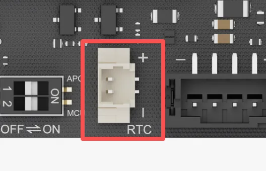
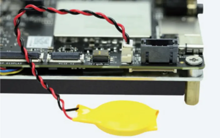
RTC Battery Connector
LattePanda Iota features a 3V Real-Time Clock(RTC) battery connector. This allows the board to maintain its internal clock even when the main power supply is completely disconnected.
Key Specifications
- Connector Type: 2-Pin, 1.25mm Pitch
- Nominal Voltage: 3.0V
- Included Battery: CR2032 Coin Cell (with pre-soldered wire and connector)
Warning
- Do not connect batteries exceeding 3.3V.
- Ensure correct polarity when inserting the battery.
Power Input Connector
In addition to the Type-C port, this connector can also be used to power the LattePanda board, making it ideal for integration into custom enclosures or systems with existing DC power.
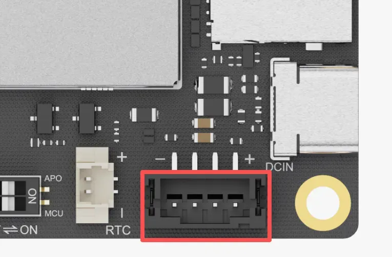
-
Connector Type: 4-Pin, 2.0mm Pitch
-
Please refer to the Power Option section for details.
GPIO Header
LattePanda Iota features a comprehensive 36-pin GPIO header, serving as a versatile interface for system control, peripheral expansion, and custom hardware integration. It provides direct access to a wide range of signals, including those from the onboard RP2040 MCU, USB 2.0 lanes, system status indicators, and audio outputs.
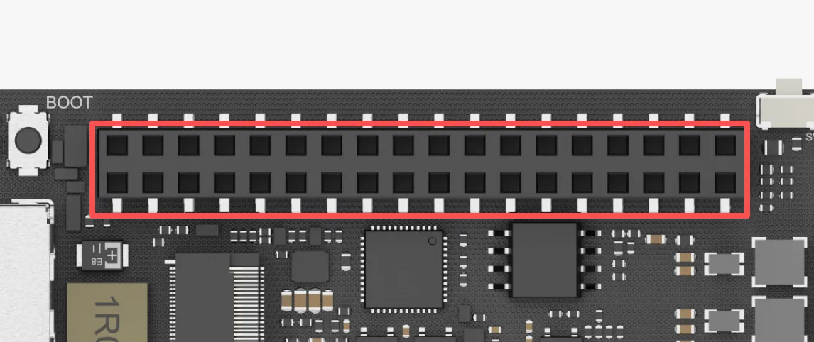
Key Specifications
- Header Type: 2x18 Female Header
- Pitch: 2.54mm (0.1 inch)
- Total Pins: 36
Pinout Definition
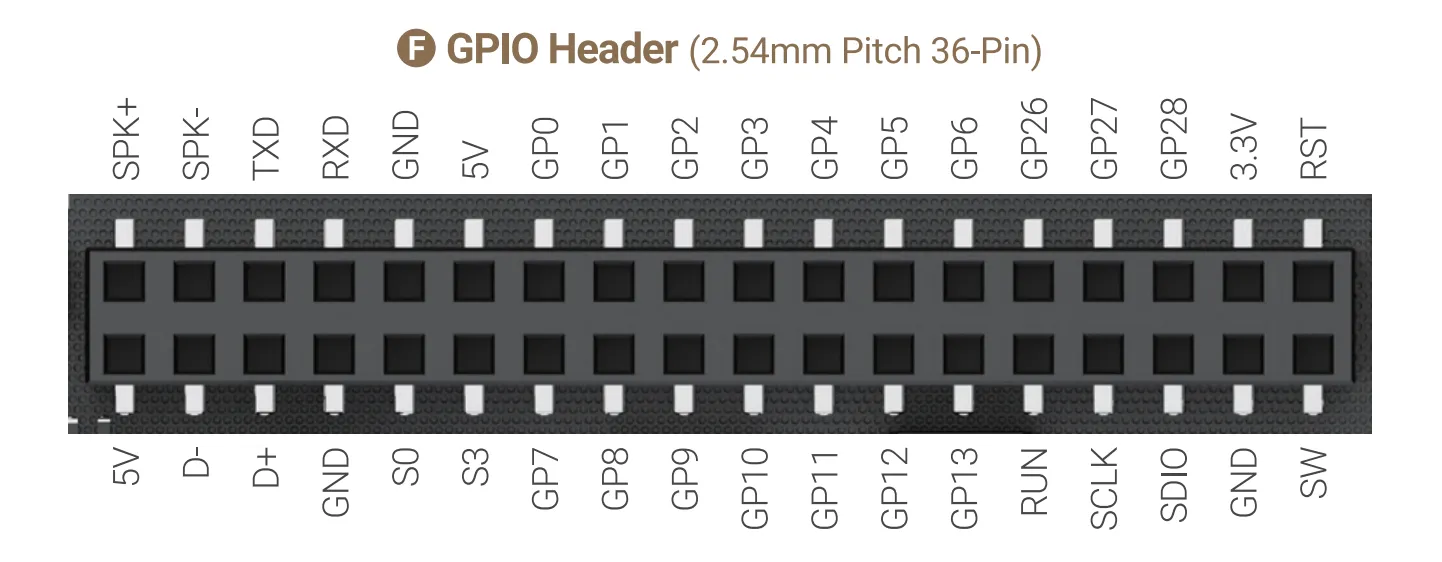
| Pin Name | Type | I/O Level | Description |
|---|---|---|---|
| SPK+ | Output | Speaker Audio Output, Positive | |
| SPK- | Output | Speaker Audio Output, Negative | |
| TXD | Output | 3.3V | Serial Port Transmit typically mapped as COM1 in Windows or /dev/ttyS0 in Linux |
| RXD | Floating Input | 3.3V | Serial Port Receive typically mapped as COM1 in Windows or /dev/ttyS0 in Linux |
| GND | Power | Ground | |
| 5V | Power | 5V Power Output 1 Current Limit: 0.5A Do not connect to 5V Power Output 2 | |
| GP0 ~ 6 | Input/Output | 3.3V | RP2040 GPIO 0~6 |
| GP26 ~ 28 | Input/Output | 3.3V | RP2040 GPIO 26~28 Multiplexed as: ADC Input each pin in parallel with a 100nF capacitor |
| 3.3V | Power | RP2040's 3.3V Power Output Current Limit: 1.2A | |
| RST | Pull-up Input | 3.3V | System Reset Pull this pin low is equivalent to press RST button. |
Note
GPIO26 to GPIO28 of the RP2040 can be muxed as ADC input. To ensure stable ADC sampling values, these pins are paralleled with 100nF capacitors, which can affect rapidly changing signals such as I2C. If using I2C, please avoid these three GPIO pins and choose alternative GPIO pins instead.
| Pin Name | Type | I/O Level | Description |
|---|---|---|---|
| 5V | Power | 5V Power Output 2 Current Limit: 1.2A Do not connect to 5V Power Output 1 | |
| D- | Input/Output | USB 2.0 Data- Native to the Porcessor's PCH | |
| D+ | Input/Output | USB2.0 Data+ Native to the Porcessor's PCH | |
| GND | Power | Ground | |
| S0 | Output | 3.3V | Running State Indicator Output HIGH only when OS is running |
| S3 | Output | 3.3V | Sleeping State Indicator Output HIGH only when OS is sleeping |
| GP7 ~ 13 | Input/Output | 3.3V | RP2040 GPIO 7~13 |
| RUN | Input | 3.3V | RP2040 Reset, Activate Low |
| SCLK | Input/Output | 3.3V | RP2040 SWCLK |
| SDIO | Input/Output | 3.3V | RP2040 SWDIO |
| GND | Power | Ground | |
| SW | Pull-up Input | 3.3V | System Power Switch Pull this pin low is equivalent to press PWR button. |
Speaker Audio Output Pins
The SPK+ and SPK- pins form a speaker audio output channel(monophonic). It can deliver up to 2 Watt (RMS) / 4 Ω. You can connect a speaker directly to play sound.
When headphones are inserted, the audio output automatically switches to the headphone jack.
Serial Port TXD RXD Pins
- The
TXDandRXDpins are derived from the onboard super I/O chip, which is typically mapped asCOM1in Windows or/dev/ttyS0in Linux. - It supports serial port redirection.
- Baud Rate: up to 115200
RP2040 GPIO Pins
- RP2040 communicates with Intel N150 Processor via USB 2.0 CDC (appears as a serial device)
- 3.3V I/O Level
- The GPIO pins of the RP2040 are directly exposed, without series resistors or parallel capacitors.
- Please refer to the rp2040_programming section for programming guide.
USB 2.0 Pins
- D+ , D- and power pins exposed for custom USB device integration.
- It can be used to interface with USB flash drive, USB-to-serial converters, custom HID devices, etc.
-
It is native to the Porcessor's PCH and does not pass through any USB hub chip.
-
You can also connect our dedicated 4G LTE Expansion Board to expand cellular connectivity.
S0 S3 Status Indication Pins
The S0 and S3 pins can indicate the operating system's current state through different output voltages. Thus, the operating system status can be obtained by reading these voltages or by connecting LED indicators.
The pins are already connected in series with 200Ω current-limiting resistors, so most LEDs(through-hole) can be attached directly without risk of burning out.
The voltage of these pins in different states are shown as follows:
| Run | Sleep | Hibernate | Shut Down | |
|---|---|---|---|---|
| S0 Pin | High | Low | Low | Low |
| S3 Pin | Low | High | Low | Low |
Power Management Connector
LattePanda Iota equips a power management expansion connector, designed as a reserved connecor for integrating with advanced power control expansion boards, such as a UPS (Uninterruptible Power Supply) expansion board.
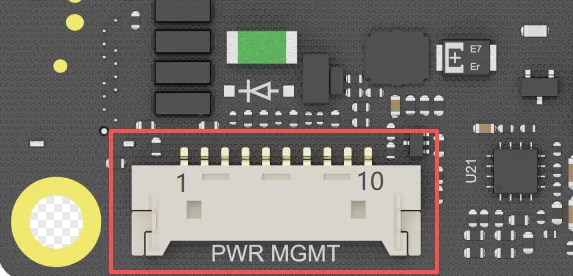
Key Specifications
- Connector Type: 10-Pin, 1.25mm Pitch
- Communication Protocol: USB 2.0
- Primary Function: To connect with a dedicated power management expansion board
Pinout Definition
| Pin | Signal Name | Type | Description |
|---|---|---|---|
| 1 | VIN | Power | DC Power Input Input Range: 9 ~15V |
| 2 | VIN | Power | same as above |
| 3 | VIN | Power | same as above |
| 4 | STATE | Output | OS State Indicator Output 3.3V only when OS is running or sleeping |
| 5 | SW | Open-drain Output | When the SW button of LattePanda is pressed, this pin is pulled LOW(0V). |
| 6 | USB_DN | Input/Output | USB 2.0 Data- Native to the Porcessor's PCH |
| 7 | USB_DP | Input/Output | USB 2.0 Data+ Native to the Porcessor's PCH |
| 8 | GND | Power | Ground |
| 9 | GND | Power | same as above |
| 10 | GND | Power | same as above |
Compatible Exp. Board
For mission-critical applications — such as data logging, remote monitoring, or edge servers — the LattePanda UPS Exp. Board (DFR1247) delivers seamless battery backup and intelligent power management.
It is a plug-and-play uninterruptible power supply module designed for the LattePanda IOTA. Using the HID-UPS protocol, it is automatically recognized as a battery in Windows 10 and 11 without drivers or programming.
For detailed step-by-step assembly and configuration instructions, please refer to the LattePanda UPS Exp. Board (DFR1247) Tutorial.
Fan Connector
LattePanda Iota is equipped with a 4-pin fan connector to support active cooling solutions, ensuring optimal performance under sustained load. The connector enables automatic, temperature-based fan speed control via PWM.
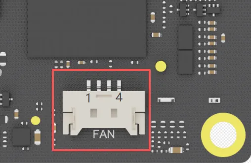
Key Specifications
- Connector Type: 4-Pin, 1.25mm Pitch
- Operating Voltage: 5V DC
- Control Method: PWM
Pinout Definition
| Pin | Signal | Wire Color (Typical) | Description |
|---|---|---|---|
| 1 | GND | Black | Ground |
| 2 | 5V | Red | 5V Power Supply for the fan |
| 3 | TACH | Yellow | Tachometer signal (provides fan speed feedback) |
| 4 | PWM | Blue | PWM control signal (input from the board to the fan) |
Compatible Fan
For a hassle-free, optimized cooling solution, we recommend using official LattePanda Iota Active Cooler(FIT1027). It is designed to fit the board and connector perfectly, providing enough thermal performance out of the box.