Fan
LattePanda Mu x86 compute module provides 2 independent fan interfaces, supporting PWM speed control and RPM monitoring (Tachometer).
- CPU_FAN: Dedicated for the CPU cooler.
- SYS_FAN: Generic system chassis fan.
Design Guidelines
Pin Definition
| Pin Name | Pin Number | Note |
|---|---|---|
| FAN2_CTL | 2 | CPU Fan PWM |
| FAN2_TAC | 4 | CPU Fan Tacho |
| FAN3_CTL | 6 | SYS Fan PWM |
| FAN3_TAC | 8 | SYS Fan Tacho |
PWM Signal
The PWM output pins on the module feature integrated 4.7kΩ pull-up resistors (to 3.3V). No external pull-up is required on the carrier board.
It is recommended to place a 100Ω series resistor in the PWM signal path for current limiting.
Tachometer Signal
The TAC pins are Open-Drain Input requiring external pull-up and protection circuitry. The design varies depending on the fan voltage (5V vs. 12V).
Warning
All TAC pins can tolerate only 5V!
Critical Design Rules
-
Pull-up Source:
- The TAC signal should be pulled up to the Fan's Operating Voltage. The typical value of this pull-up resistor is 4.7KΩ.
- It is NOT RECOMMENDED to pull up a 12V fan's TAC signal to a 5V or 3.3V rail on the carrier board.
-
Surge Protection:
- A Diode (e.g., 1N4148, 1N5819) is recommended in parallel with the pull-up resistor.
- Function: Clamps voltage surges. If the TAC signal exceeds the supply voltage, the diode conducts, diverting the surge current to the power rail.
-
Level Shifting:
- 12V Fan: A resistive voltage divider (multiple resistors in series) is MANDATORY to step down the 12V tachometer signal to a safe logic level (≤ 5V) compatible with the compute module.
- 5V Fan: Since the voltage is within the safe range, the divider can be simplified.
-
Power Control
- In sleep mode, the fan's power should be turned off.
Recommended Fan Circuit
5V Fan
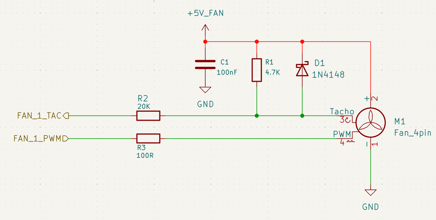
In the image above, resistor R2 can be selected from 1K to 30K. If space is tight, this resistor can also be omitted.
12V Fan
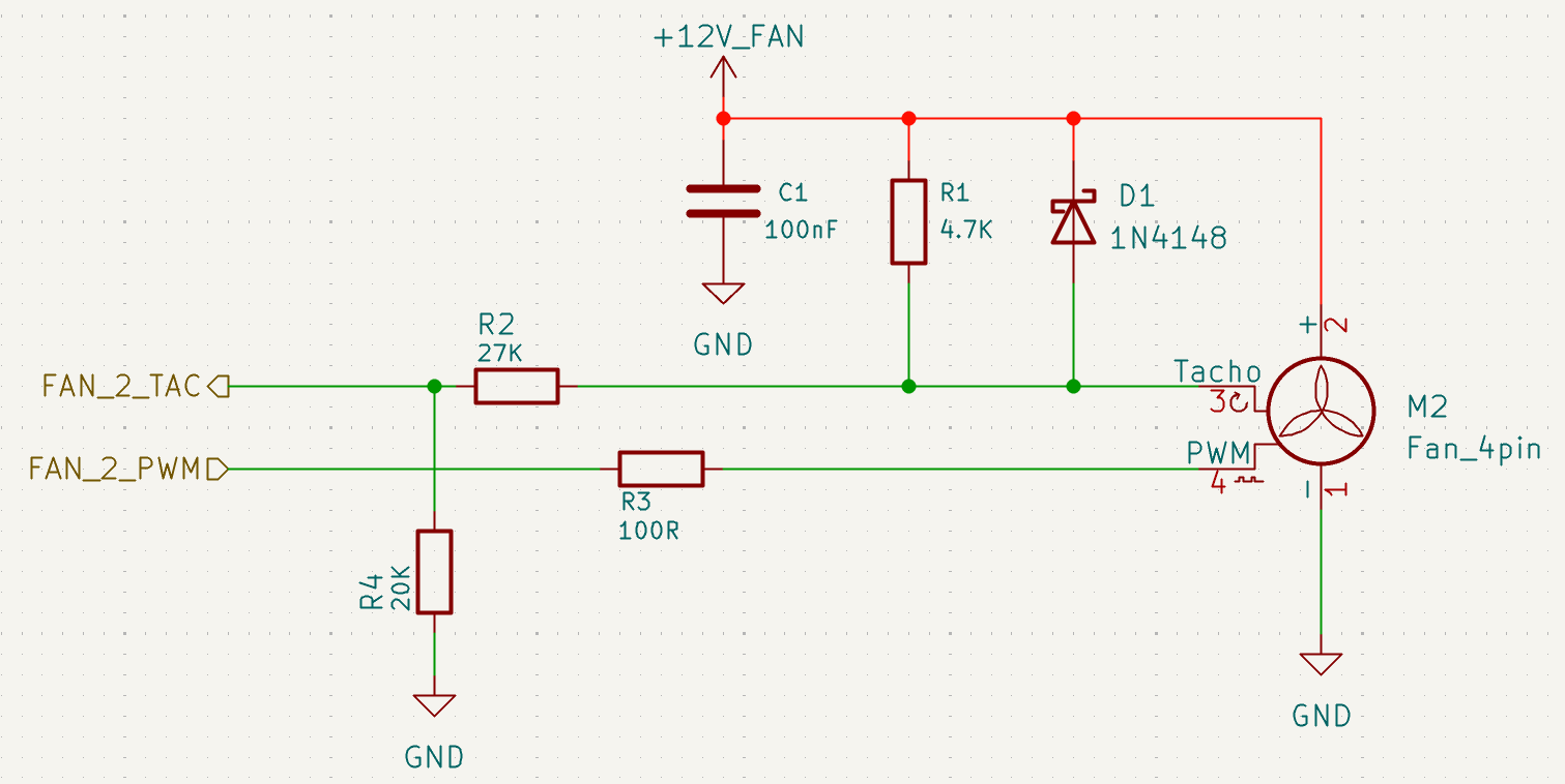
In the image above, resistor R4 is part of a voltage divider, ensuring that the voltage at the TAC input pin does not exceed 5V, and therefore cannot be omitted. Based on this principle, the specific resistance values of R2 and R4 can be adjusted according to actual conditions.
Power Control
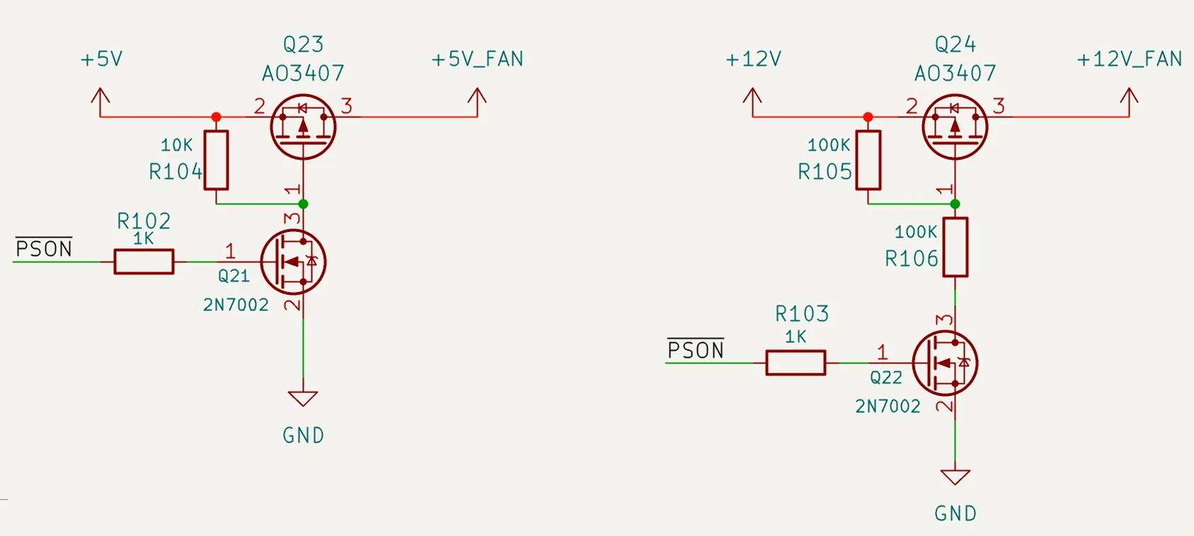
In sleep mode, the PWM signal is disabled. If the fan's power remains on, the fan will run at full speed. To prevent this, a PMOS and NMOS combination can be used as a power switch controlled by the PSON signal, as shown in the image above. This arrangement ensures the fan's power is turned off during sleep mode.