HDMI 2.1
LattePanda Mu x86 compute module derives up to 3 HDMI outputs from the DDIB, TCP0, and TCP1 interfaces, supports up to 4K @ 60Hz.
Interface Configuration
-
HDMI signals(operating in TMDS mode) can only be configured from DDIB, TCP0, or TCP1.
-
The default BIOS enables DDIB and TCP0 as HDMI.
To configure TCP1 as HDMI(TMDS mode), a specific BIOS firmware must be flashed. Dynamic switching via the BIOS menu is not supported.
Note
Due to processor limitations, a maximum of three displays is supported simultaneously.
Design Guidelines
Pin Definition
| Interface Name | Pin Number |
|---|---|
| DDIB (TDMS Differential Pair) | 197, 199, 203, 205, 209, 211, 215, 217 |
| DDIB DDC & HPD | 169, 171, 183 |
| TCP0 (TDMS Differential Pair) | 227, 229, 233, 235, 239, 241, 245, 247 |
| TCP0 DDC & HPD | 177, 179, 187 |
| TCP1 (TDMS Differential Pair) | 220, 222, 226, 228, 232, 234, 238, 240 |
| TCP1 DDC & HPD | 173, 175, 185 |
AC Coupling & Pull-down Bias
Note
On LattePanda Mu compute module, DDIB,TCP0 and TCP1 signal lines do not integrate AC coupling capacitors.
Intel's reference design requires a specific AC Coupling + Pull-down Bias topology.
- AC Coupling: A 100nF (0.1uF) capacitor must be placed in series on all four TMDS differential pairs. 0402 or smaller package is recommended to minimize parasitics.
- Pull-down Bias: After the capacitor (connector side), each TMDS signal line must be pulled down to GND via a 470Ω resistor.
-
Switch Control: The ground connection of all 470Ω resistors should be gathered and controlled by an NMOS. The NMOS turns ON (enabling the pull-downs) ONLY when the system is in the Working (S0) state.
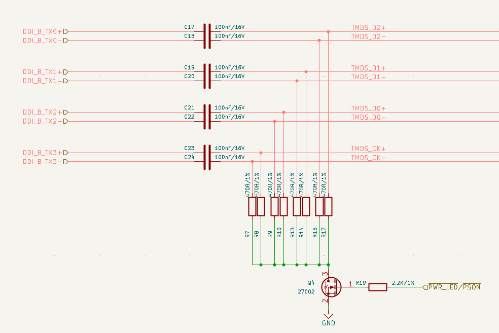
Why are 470Ω pull-down resistors mandatory?
This is the standard design required by Intel. Omitting the 470Ω resistor will cause the signal eye diagram to fail and lead to compatibility issues.
Polarity Check
HDMI TMDS differential pairs do not support polarity inversion.
Strict polarity matching must be implemented on the carrier board. Ensure that Positive (+) maps to Positive (+) and Negative (-) maps to Negative (-), as illustrated in the figure below.
+---------------------+                            +---------------------+
|  Compute Module     |                            |   HDMI Connector    |
|                     |                            |                     |
|  [TMDS_DATA_P] (+)  | O========================O |  [TMDS_DATA_P] (+)  |
|                     |                            |                     |
|  [TMDS_DATA_N] (-)  | O========================O |  [TMDS_DATA_N] (-)  |
|                     |                            |                     |
+---------------------+                            +---------------------+
          ^                                                   ^
          |                                                   |
          +----------- STRICT 1:1 MAPPING REQUIRED -----------+
                       Do NOT Swap P & N Signals!
Level Shifter
DDC(I2C) andHPDsignals from compute module are 3.3V.- HDMI standard requires 5V logic levels.
- Direct connection is prohibited. A level shifting circuit (using NMOS or dedicated chips) must be implemented on the carrier board.
No AUX Signal
When operating in TMDS mode, the AUX signals are unused, so they should be left not connected.
For example, when DDIB is operating in TMDS mode, the following pins should be NC.
Pin 191: DDIB_AUX_N
Pin 193: DDIB_AUX_P
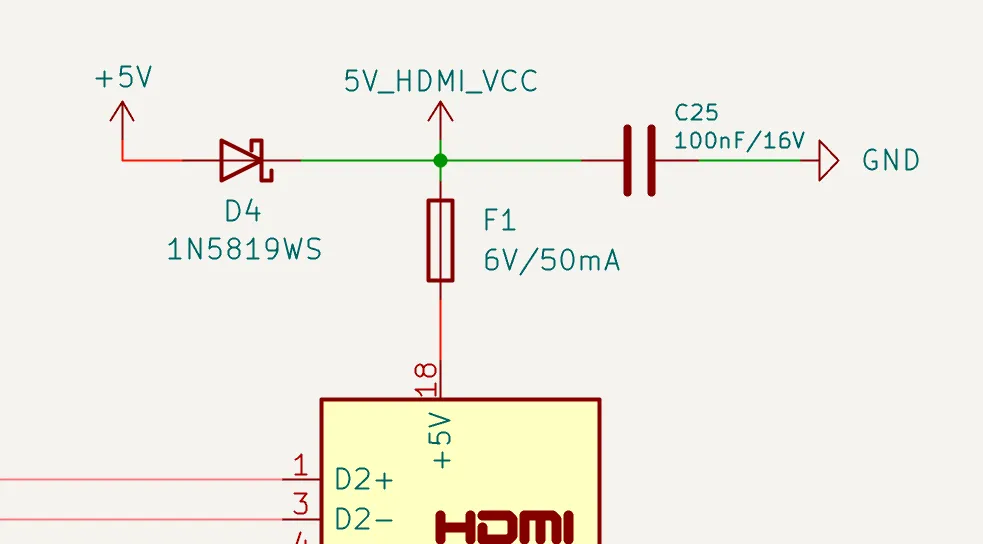
Power Backflow Prevention
A diode must be connected in series between the system power and the 5V pin of the HDMI connector to prevent power conflict between the host and the device. As shown below, diode D4 cannot be omitted.
However, the resettable fuse F1 is optional if space is constrained.
ESD Protection
Since HDMI ports are subject to frequent hot-plugging, they are vulnerable to Electrostatic Discharge (ESD). And TMDS signals are extremely sensitive to capacitance. So Ultra-low capacitance ESD protection diodes are mandatory.
| Signal Type | Recommended Specs |
|---|---|
| High Speed (TMDS) | Junction Capacitance: < 0.18 pF Reverse Working Voltage: 3.3 V |
| Low Speed (DDC/HPD) | Junction Capacitance: < 3 pF Reverse Working Voltage: 5.5V or 6 V |
Layout Guidelines
| Parameter | Requirement |
|---|---|
| Differential Impedance | 100Ω |
| Intra-pair Skew | < 5 mil |
| Inter-pair Skew | < 13 mm |
| AC Cap for TMDS | 100nF nominal |
| Bias Resistor for TMDS | 470Ω nominal |
| AC Cap & Bias Resistor Placement | As close to HDMI connector as possible (<25 mm) |
| Reference Plane | Continuous GND Recommended |
Spacing & Crosstalk
-
Trace Type: Microstrip Differential Pair
-
Recommended Pair-to-Pair Spacing: ≥ 5W (where W is trace width).
To ensure signal integrity for HDMI 2.1 (4K@60Hz) , a spacing of at least 5W is required to strictly minimize crosstalk.
-
Recommended General Spacing: Maintain at least 5W spacing between high-speed TMDS pairs and other signals (DDC, HPD, Power).
Differential Pair Net Length
The follow tables list the LattePanda Mu compute module track-length for the DDIB, TCP0 and TCP1 interfaces.
| Net Name | Net Length(mil) |
|---|---|
| DDIB_TX0_P | 1856 |
| DDIB_TX0_N | 1857 |
| DDIB_TX1_P | 1794 |
| DDIB_TX1_N | 1795 |
| DDIB_TX2_P | 1804 |
| DDIB_TX2_N | 1804 |
| DDIB_TX3_P | 1791 |
| DDIB_TX3_N | 1792 |
| DDIB_AUX_P | 1784 |
| DDIB_AUX_N | 1787 |
| Net Name | Net Length(mil) |
|---|---|
| TCP1_TXRX0_P | 2139 |
| TCP1_TXRX0_N | 2141 |
| TCP1_TXRX1_P | 2228 |
| TCP1_TXRX1_N | 2231 |
| TCP1_TX0_P | 1965 |
| TCP1_TX0_N | 1968 |
| TCP1_TX1_P | 2087 |
| TCP1_TX1_N | 2091 |
| TCP1_AUX_P | 2162 |
| TCP1_AUX_N | 2161 |
| Net Name | Net Length(mil) |
|---|---|
| TCP0_TXRX0_P | 2339 |
| TCP0_TXRX0_N | 2340 |
| TCP0_TXRX1_P | 2017 |
| TCP0_TXRX1_N | 2017 |
| TCP0_TX0_P | 1956 |
| TCP0_TX0_N | 1958 |
| TCP0_TX1_P | 2090 |
| TCP0_TX1_N | 2094 |
| TCP0_AUX_P | 1943 |
| TCP0_AUX_N | 1945 |