USB 3.2
LattePanda Mu x86 compute module provides up to 4 independent USB 3.2 Gen 2 lanes.
- Each supports SuperSpeed USB 10 Gbps, backward compatible with SuperSpeed USB 5Gbps.
- All ports operate in Host Mode ONLY. USB OTG is NOT supported.
Lane Configuration
-
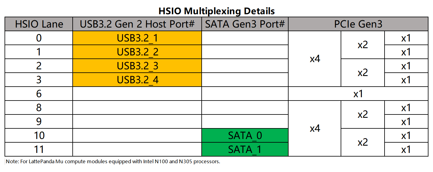
USB 3.2 signals only can be multiplexed from HSIO0 ~ HSIO3.
-
The default BIOS enables HSIO 0 and HSIO 1 as USB 3.2 lane.
Note
- HSIO lanes are multiplexed resources. Once a lane is configured as USB 3.2, it cannot be used as PCIe.
- Customized BIOS firmware is required for any HSIO configuration changes. Dynamic switching via the BIOS menu is not supported. For example, to configure HSIO 2 or HSIO 3 lane as USB 3.2, a specific BIOS firmware must be flashed.
- For more details, please see the HSIO Multiplexing chapter.
Design Guidelines
Pin Definition
| Lane Name | Pin Number |
|---|---|
| HSIO 0 | 13, 15, 16, 18 |
| HSIO 1 | 19, 21, 22, 24 |
| HSIO 2 | 25, 27, 28, 30 |
| HSIO 3 | 31, 33, 34, 36 |
AC Coupling
Note
On LattePanda Mu compute module, HSIO lane signal lines do not integrate AC coupling capacitors.
USB 3.2 links require AC coupling.
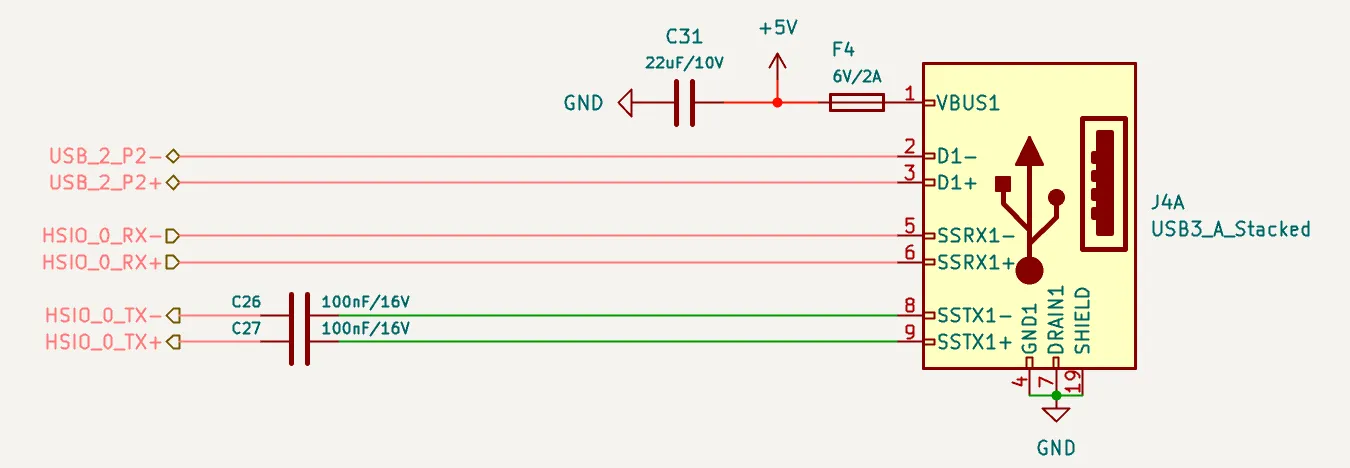
-
SSTX: Must place 0.1uF (100nF) series capacitors. 0402 or smaller package is recommended to minimize parasitics.
-
SSRX: No capacitors required (they are included in the device side).
+---------------------+       +---------------------+
|    Carrier Board    |       |    USB3.2  Device   |
|                     |       |                     |
| SSTX+ ---||---------o-->>---o--- SSRX+            |
|        0.1uF        |       |                     |
|                     |       |                     |
| SSTX- ---||---------o-->>---o--- SSRX-            |
|        0.1uF        |       |                     |
|                     |       |                     |
|                     |       |  0.1uF              |
| SSRX+ --------------o--<<---o---||--- SSTX+       |
|       (NO CAP)      |       |                     |
|                     |       |  0.1uF              |
| SSRX- --------------o--<<---o---||--- SSTX-       |
|       (NO CAP)      |       |                     |
+---------------------+       +---------------------+
Polarity Check
Intel's reference design document does not explicitly confirm support for polarity inversion on USB 3.2 differential pairs.
Therefore, implement strict polarity matching on the carrier board. Do NOT Swap P & N Signals. As shown in the figure above.
Pairing Requirement
A standard USB 3.2 Type-A connector consists of two parts:
- SuperSpeed Signals: USB 3.2 Lane (SSTX / SSRX) from HSIO.
- HighSpeed Signals: USB 2.0 Lane (D+ / D-).
A USB 3.2 lane can be paired with any USB 2.0 lane (except USB2_P6). There is no fixed hardware binding between them.
USB2_P6 Restriction
As USB2.0 chapter noted, USB2_P6 is reserved for USB Type-C port by default and cannot be used as a generic USB 2.0 companion for a USB 3.2 port without BIOS modification.
Host's Perspective
In our schematics (such as the DFR1142 Lite Carrier), the USB 3.2 Type-A female connector pinout is defined from the host's perspective.
When routing, connect the host's TX signals directly to the connector's TX pins, and the RX signals to the RX pins. Do not swap these signals. As shown in the figure below.
Power Requirement
One USB 3.2 port (single device only): Recommended minimum current is 1.0A.
ESD Protection
Since USB ports are subject to frequent hot-plugging, they are vulnerable to Electrostatic Discharge (ESD). And USB 3.2 10Gbps signals are extremely sensitive to capacitance. So Ultra-low capacitance ESD protection diodes are mandatory.
- Recommended Specs:
- Junction Capacitance: < 0.18 pF
- Reverse Working Voltage: 3.3V
Layout Guidelines
| Parameter | Requirement |
|---|---|
| Differential Impedance | 90Ω |
| Intra-pair Skew | < 5 mil |
| Inter-pair Skew | Length matching between the SSTX pair and SSRX pair is NOT required. |
| SSTX AC Cap for USB 3.2 | 100nF nominal |
| SSTX AC Cap Placement | As close to USB connector as possible (<25 mm) |
| Reference Plane | Continuous GND Recommended |
Spacing & Crosstalk
-
Trace Type: Microstrip Differential Pair
-
Recommended Pair-to-Pair Spacing: ≥ 5W (where W is trace width).
To ensure signal integrity for USB 3.2 (10Gbps) , a spacing of at least 5W is required to strictly minimize crosstalk.
-
Recommended General Spacing: Maintain at least 5W spacing between high-speed SSTX/SSRX pairs and other signals (USB 2.0 D+/D-, Power).