Linux GPIO Programming
This chapter guides you through configuring and programming the UART, I2C, and GPIO ports on the LattePanda Mu compute module under the Linux OS.
The sample code and procedures in this tutorial are based on Ubuntu 24.04 LTS.
UART
Pinout Assignment
The LattePanda Mu compute module provides up to 4 UART ports.
The pin locations and corresponding system port mappings are detailed below:
| Pin#(Edge Connector) | Pin Name | Note |
|---|---|---|
| 10 | SIO_UART_TX | UART exposed from SuperIO; Typically mapped as COM1 in Windows or /dev/ttyS0 in Linux |
| 12 | SIO_UART_RX | As above |
| 139 | SOC_UART0_TXD | UART0 exposed from PCH; Typically mapped as COM2 in Windows or /dev/ttyS4 in Linux |
| 137 | SOC_UART0_RXD | As above |
| 143 | SOC_UART1_TXD | UART1 exposed from PCH; Typically mapped as COM3 in Windows or /dev/ttyS5 in Linux |
| 141 | SOC_UART1_RXD | As above |
| 138 | SOC_UART2_TXD | UART2 exposed from PCH; Typically mapped as COM4 in Windows or /dev/ttyS6 in Linux |
| 140 | SOC_UART2_RXD | As above |
Logic Level
All the UART pins mentioned above use 3.3V levels. Do not apply voltages higher than 3.3V.
BIOS Requirement
To ensure the port mapping matches the table above, the BIOS version must be S70NC1R200-8G-A or the 16G variant or the SATA variant (Build Date: 2025/12/19) or higher.
Older BIOS versions may cause duplicate serial port mappings or mappings that don't match the table above. If upgrading from an older BIOS version:
- Windows: It is recommended to uninstall all COM devices in Device Manager and reboot the system to refresh the mapping.
- Linux: A simple system reboot is sufficient.
Programming with Python pyserial
-
Regular users must be added to the
dialoutgroup to access serial ports, otherwise, a permission error will occur.This change takes effect after a restart or re-login.sudo usermod -aG dialout $USER -
Install dependencies
pip install pyserial -
Complete sample code for serial loopback(
uart_tx_rx.py)import serial import time DEVICE = '/dev/ttyS0' #SIO_UART BAUD_RATE = 9600 def main(): try: # Open serial port ser = serial.Serial( port=DEVICE, baudrate=BAUD_RATE, bytesize=serial.EIGHTBITS, # 8 data bits parity=serial.PARITY_NONE, # No parity stopbits=serial.STOPBITS_ONE, # 1 stop bit timeout=1 # Read timeout (seconds) ) print(f"Serial port opened: {ser.name}") tx_data = b"Hello from Python UART (ttyS0, 9600)\r\n" # TX: Send data ser.write(tx_data) print(f"Sent: {tx_data}") # Wait a bit for response time.sleep(0.5) print("Waiting for data...") rx_data = ser.read(128) #RX: Receive data, Read up to 128 bytes if rx_data: print(f"Received: {rx_data}") else: print("No data received") except Exception as e: print(f"Error: {e}") finally: if 'ser' in locals() and ser.is_open: ser.close() # Close serial port print("Serial port closed") if __name__ == "__main__": main() -
Short-circuit the TX and RX pins of the SIO_UART, then run the following command to view the looped-back data.
python3 uart_tx_rx.py
Programming with C termios
-
Regular users must be added to the
dialoutgroup to access serial ports, otherwise, a permission error will occur.This change takes effect after a restart or re-login.sudo usermod -aG dialout $USER -
Install dependencies
sudo apt install build-essential -
Complete sample code for serial loopback(
uart_tx_rx.c)#include <stdio.h> #include <stdlib.h> #include <string.h> #include <unistd.h> #include <fcntl.h> #include <termios.h> #include <errno.h> #define DEVICE "/dev/ttyS0" #define BAUDRATE B9600 int main() { int fd; // Open serial port fd = open(DEVICE, O_RDWR | O_NOCTTY); if (fd < 0) { perror("Failed to open serial port"); return -1; } printf("Serial port opened: %s\n", DEVICE); // Configure serial port struct termios options; memset(&options, 0, sizeof(options)); // Get current attributes if (tcgetattr(fd, &options) != 0) { perror("tcgetattr failed"); close(fd); return -1; } // Set baud rate cfsetispeed(&options, BAUDRATE); cfsetospeed(&options, BAUDRATE); // Configure: 8N1 (8 data bits, no parity, 1 stop bit) options.c_cflag &= ~PARENB; // Disable parity options.c_cflag &= ~CSTOPB; // 1 stop bit options.c_cflag &= ~CSIZE; options.c_cflag |= CS8; // 8 data bits options.c_cflag |= CREAD | CLOCAL; // Enable receiver, ignore modem control lines // Raw input/output mode options.c_lflag &= ~(ICANON | ECHO | ECHOE | ISIG); // Non-canonical mode options.c_iflag &= ~(IXON | IXOFF | IXANY); // Disable software flow control options.c_oflag &= ~OPOST; // Raw output // Set read timeout options.c_cc[VMIN] = 0; // Minimum number of bytes options.c_cc[VTIME] = 10; // Timeout in deciseconds (1 second) // Apply settings if (tcsetattr(fd, TCSANOW, &options) != 0) { perror("tcsetattr failed"); close(fd); return -1; } // --------------------------- // TX: Send data // --------------------------- char *tx_data = "Hello from C UART (ttyS0, 9600)\r\n"; int len = strlen(tx_data); int written = write(fd, tx_data, len); if (written < 0) { perror("Write failed"); } else { printf("Sent %d bytes: %s", written, tx_data); } // Wait before reading usleep(500000); // 500 ms // --------------------------- // RX: Receive data // --------------------------- char buffer[128]; memset(buffer, 0, sizeof(buffer)); int n = read(fd, buffer, sizeof(buffer)); if (n < 0) { perror("Read failed"); } else if (n == 0) { printf("No data received\n"); } else { printf("Received %d bytes: %s\n", n, buffer); } // Close serial port close(fd); printf("Serial port closed\n"); return 0; } -
Short-circuit the TX and RX pins of the SIO_UART, then run the following command to view the looped-back data.
gcc uart_tx_rx.c -o uart_tx_rx
./uart_tx_rx
I2C
Pinout Assignment
The LattePanda Mu compute module provides up to 4 I2C ports.
The pin locations are detailed below:
| Pin#(Edge Connector) | Pin Name |
|---|---|
| 154 | I2C2_SCL |
| 156 | I2C2_SDA |
| 150 | I2C3_SCL |
| 152 | I2C3_SDA |
| 146 | I2C4_SCL |
| 148 | I2C4_SDA |
| 142 | I2C5_SCL |
| 144 | I2C5_SDA |
Note
If you are using the DFR1141 Full Eval Carrier, an I2C device(IT8851 chip) with address 0x40 is already present on the I2C2 port. Therefore, avoid connecting any other I2C device with the same address to this port.
Logic Level
All the I2C pins mentioned above are pulled up to 3.3 V via 2.2kΩ resistors inside the compute module. Do not apply voltages higher than 3.3V.
Programming in Linux
Please refer to the "How to Use the I2C Port on LattePanda Mu in Ubuntu OS" post in our forum.
GPIO
Pinout Assignment
The LattePanda Mu compute module currently provides up to 17 GPIO pins that can be configured as either inputs or outputs. You can execute scripts within the system to control these GPIOs to read signals from or send signals to peripheral devices.
The pin locations and their default functions are listed in the table below:
| Pin#(Edge Connector) | Pin Name | Default Function |
|---|---|---|
| 126 | GPP_F12 | GPIO |
| 124 | GPP_F13 | GPIO |
| 122 | GPP_F14 | GPIO |
| 120 | GPP_F15 | GPIO |
| 118 | GPP_F16 | GPIO |
| 119 | GPP_E0 | WWAN_PWR_EN |
| 121 | GPP_A12 | CAM_PWR_EN |
| 139 | SOC_UART0_TXD / GPP_H11 | UART0_TXD |
| 137 | SOC_UART0_RXD / GPP_H10 | UART0_RXD |
| 143 | SOC_UART1_TXD / GPP_D18 | UART1_TXD |
| 141 | SOC_UART1_RXD / GPP_D17 | UART1_RXD |
| 138 | SOC_UART2_TXD / GPP_F2 | UART2_TXD |
| 140 | SOC_UART2_RXD / GPP_F1 | UART2_RXD |
| 128 | GPP_D0 | WWAN_PWR_EN |
| 130 | GPP_D1 | WWAN_RST |
| 132 | GPP_D2 | IT8851_INT |
| 134 | GPP_D3 | CAM_PWR_EN |
GPIO Features
-
3.3V I/O voltage levels
-
Floating input or push-pull output
-
Defaults to high-impedance state after OS boot or reboot
-
Routed directly from the processor PCH
Warning
Since these GPIOs originate directly from the processor's PCH, special care must be taken during use.
Overvoltage, overcurrent, and short circuits are strictly prohibited, as any damage to the pins is irreparable.
BIOS Requirement
GPIO function requires BIOS support. Please ensure that the BIOS version used by your LattePanda Mu module is S70NC1R200-8G-A or the 16G variant or the SATA variant (Build Date: 2025/12/19) or higher.
If you are using an older version such as LP-BS-S70NC1R200-SR-B, please refer to the Update BIOS Firmware section to complete a BIOS update.
Switch Multiplexed Pins to GPIO Mode
GPP_F12 to GPP_F16 pins can be used directly as GPIOs without requiring any BIOS configuration.
The remaining pins are not set to GPIO by default and must be switched to GPIO mode in the BIOS.
Switching Steps:
-
Power-on or restart LattePanda board, press Del to enter the BIOS setup.
-
Navigate to the
GPIO Configurationoption via the following path:Advanced -> GPIO Configuration. -
Configure the required pins to GPIO mode.
For example: If you do not need to use UART2 but wish to use the UART2 TXD and RXD pins as GPIOs, select "GPIO" as shown in the figure below.
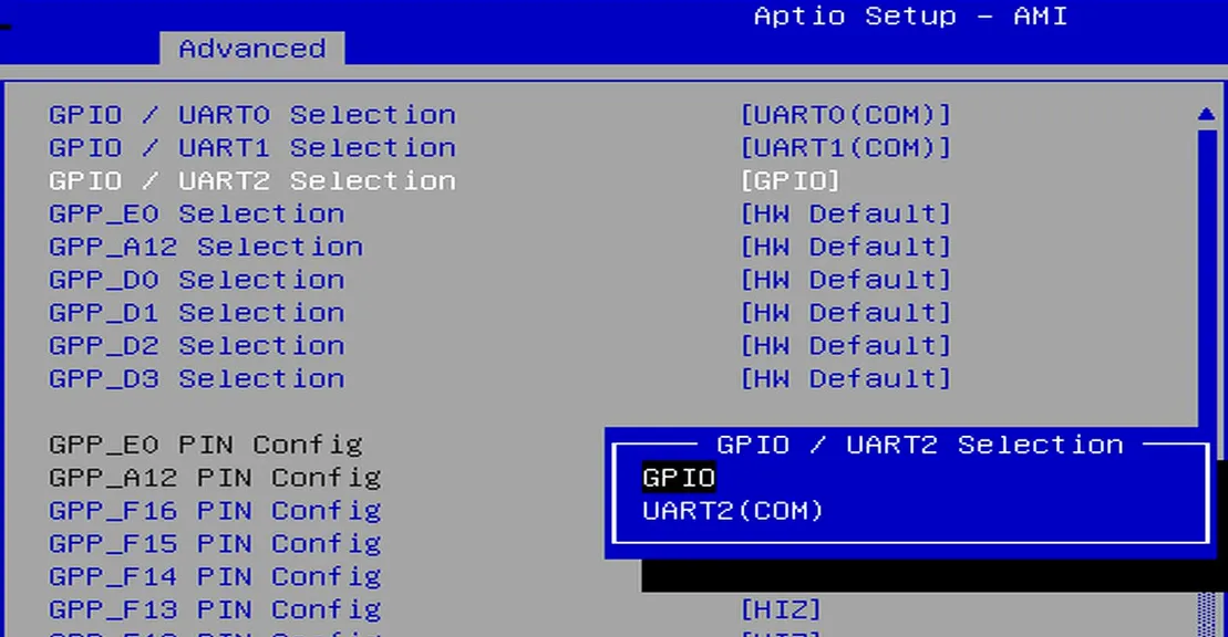
-
Navigate to the
Save & Exit pageand selectSave Changes and Exitoption to save the BIOS settings and restart the LattePanda board.
GPIO Address
For LattePanda Mu modules (Intel N100 or N305 processor), the underlying GPIO controller is mapped to gpiochip0 with the device identifier [INTC1057:00].
You can verify the controller status using the gpiodetect command from the terminal:
sudo apt update
sudo apt install gpiod
sudo gpiodetect
| Pin Name | Line Offset |
|---|---|
| GPP_F12 | 300 |
| GPP_F13 | 301 |
| GPP_F14 | 302 |
| GPP_F15 | 303 |
| GPP_F16 | 304 |
| GPP_E0 | 320 |
| GPP_A12 | 76 |
| SOC_UART0_TXD / GPP_H11 | 171 |
| SOC_UART0_RXD / GPP_H10 | 170 |
| SOC_UART1_TXD / GPP_D18 | 210 |
| SOC_UART1_RXD / GPP_D17 | 209 |
| SOC_UART2_TXD / GPP_F2 | 290 |
| SOC_UART2_RXD / GPP_F1 | 289 |
| GPP_D0 | 192 |
| GPP_D1 | 193 |
| GPP_D2 | 194 |
| GPP_D3 | 195 |
Programming with Python libgpiod
In Linux OS, the Python or C version of the libgpiod can be used for GPIO programming.
The following demonstration uses an Ubuntu OS(either version 22.04 or 24.04) to control the GPP_F12 pin as an example.
Environment Preparation
- Install the Python gpiod library
sudo apt update
sudo apt install python3-libgpiod
 This case uses gpiod library from the system repository, installed via
 apt install python3-libgpiod — not the PyPI version installed via pip install gpiod. GPIO Output
The following code sets the GPP_F12 pin to output mode and toggles the output level signal every second.
- Save the following code as a Python file, for example,
gpio_toggle_demo.py.
import gpiod
import time
import sys

# ================= Configuration =================
# Hardware: LattePanda Mu (Intel N100/N305)
# Chip: [INTC1057:00] -> gpiochip0
CHIP_NAME = 'gpiochip0'

# Pin Definition (Mapping Name to Line Offset)
PIN_GPP_F12 = 300

# Select the target pin for this demo
TARGET_LINE_OFFSET = PIN_GPP_F12
# ===============================================

def main():
    chip = None
    line = None

    try:
        # 1. Initialize Chip
        chip = gpiod.Chip(CHIP_NAME)

        # 2. Get the specific line (GPP_F12)
        line = chip.get_line(TARGET_LINE_OFFSET)

        # 3. Request Control
        # Set direction to OUTPUT
        line.request(consumer="GPIO_Toggle_Demo", type=gpiod.LINE_REQ_DIR_OUT)

        print(f"Demo Started: Blinking Pin GPP_F12 (Line {TARGET_LINE_OFFSET})...")
        print("Press Ctrl+C to stop.")

        # 4. Main Loop
        while True:
            # Set High Level
            line.set_value(1)
            print(f"[{time.strftime('%H:%M:%S')}] GPIO -> HIGH (1)")
            time.sleep(1)

            # Set Low Level
            line.set_value(0)
            print(f"[{time.strftime('%H:%M:%S')}] GPIO -> LOW  (0)")
            time.sleep(1)

    except KeyboardInterrupt:
        print("\nDemo stopped by user (Ctrl+C).")

    except Exception as e:
        print(f"An error occurred: {e}")

    finally:
        # 5. Clean up resources
        # The 'finally' block GUARANTEES this runs even after Ctrl+C
        if line:
            line.release()
            print("GPIO Line released.")
        if chip:
            chip.close()
            print("GPIO Chip closed.")

if __name__ == "__main__":
    main()
- Navigate to the directory containing the
gpio_toggle_demo.pyfile and run the following command in the terminal. You will observe theGPP_F12pin outputting high and low signals at approximately 1-second intervals.
sudo python3 gpio_toggle_demo.py
GPIO Input
The following code sets the GPP_F12 pin to input mode and read its level status at one-second intervals.
import gpiod
import time

# ================= Configuration =================
# Hardware: LattePanda Mu
# Chip: gpiochip0
# Pin: GPP_F12 -> Line Offset 300
CHIP_NAME = 'gpiochip0'
PIN_GPP_F12 = 300
# ===============================================

def main():
    chip = None
    line = None

    try:
        # 1. Initialize Chip
        chip = gpiod.Chip(CHIP_NAME)

        # 2. Get the line
        line = chip.get_line(PIN_GPP_F12)

        # 3. Request Control as INPUT
        # We specify LINE_REQ_DIR_IN for input mode
        line.request(consumer="GPIO_Input_Demo", type=gpiod.LINE_REQ_DIR_IN)

        print(f"Demo Started: Reading Input from GPP_F12 (Line {PIN_GPP_F12})...")
        print("Connect this pin to GND or VCC (3.3V) to see changes.")
        print("Press Ctrl+C to stop.")

        # 4. Main Loop
        while True:
            # Read current value (0 or 1)
            value = line.get_value()

            print(f"[{time.strftime('%H:%M:%S')}] Input Value: {value}")

            # Wait 1 second
            time.sleep(1)

    except KeyboardInterrupt:
        print("\nDemo stopped by user.")
    except Exception as e:
        print(f"Error: {e}")
    finally:
        # 5. Cleanup
        if line:
            line.release()
        if chip:
            chip.close()
        print("Resources released.")

if __name__ == "__main__":
    main()
Programming with C libgpiod
In Linux OS, the Python or C version of the libgpiod can be used for GPIO programming.
The following demonstration uses an Ubuntu OS(either version 22.04 or 24.04) to control the GPP_F12 pin as an example.
Environment Preparation
- Install the C gpiod library
sudo apt update
sudo apt install libgpiod-dev
GPIO Output
The following code sets the GPP_F12 pin to output mode and toggles the output level signal every second.
- Save the following code as a C file, for example,
gpio_toggle_demo.c.
#include <gpiod.h>
#include <stdio.h>
#include <unistd.h>
#include <signal.h>
#include <stdbool.h>

// ================= Configuration =================
// Hardware: LattePanda Mu (Intel N100/N305)
// Chip: gpiochip0
// Pin: GPP_F12 -> Line Offset 300
// ===============================================

#define CHIP_NAME "gpiochip0"
#define PIN_GPP_F12 300

// Flag for the main loop, modified by signal handler
static volatile sig_atomic_t keep_running = 1;

// Signal Handler for Ctrl+C
void signal_handler(int sig) {
    keep_running = 0;
}

int main(void) {
    struct gpiod_chip *chip;
    struct gpiod_line *line;
    int ret;

    // 1. Register signal handler (Ctrl+C)
    signal(SIGINT, signal_handler);

    // 2. Open the GPIO Chip
    chip = gpiod_chip_open_by_name(CHIP_NAME);
    if (!chip) {
        perror("Open chip failed");
        return 1;
    }

    // 3. Get the specific line
    line = gpiod_chip_get_line(chip, PIN_GPP_F12);
    if (!line) {
        perror("Get line failed");
        gpiod_chip_close(chip);
        return 1;
    }

    // 4. Request the line as OUTPUT
    // "LattePanda_C_Demo" is the consumer label visible in gpioinfo
    ret = gpiod_line_request_output(line, "GPIO_Toggle_Demo", 0);
    if (ret < 0) {
        perror("Request line as output failed");
        gpiod_chip_close(chip);
        return 1;
    }

    printf("Demo Started: Blinking Pin GPP_F12 (Line %d)...\n", PIN_GPP_F12);
    printf("Press Ctrl+C to stop.\n");

    // 5. Main Loop
    while (keep_running) {
        // Set High
        gpiod_line_set_value(line, 1);
        printf("GPIO -> HIGH (1)\n");
        sleep(1);

        if (!keep_running) break;

        // Set Low
        gpiod_line_set_value(line, 0);
        printf("GPIO -> LOW  (0)\n");
        sleep(1);
    }

    // 6. Cleanup Resources
    printf("\nReleasing resources...\n");
    gpiod_line_release(line);
    gpiod_chip_close(chip);
    printf("Done.\n");

    return 0;
}
- Navigate to the directory containing the
gpio_toggle_demo.cfile and run the following command in the terminal. You will observe theGPP_F12pin outputting high and low signals at approximately 1-second intervals.
gcc -o gpio_toggle_demo gpio_toggle_demo.c -lgpiod
sudo ./gpio_toggle_demo
GPIO Input
The following code sets the GPP_F12 pin to input mode and read its level status at one-second intervals.
#include <gpiod.h>
#include <stdio.h>
#include <unistd.h>
#include <signal.h>

// ================= Configuration =================
#define CHIP_NAME "gpiochip0"
#define PIN_GPP_F12 300
// ===============================================

static volatile sig_atomic_t keep_running = 1;

// Signal Handler for graceful exit
void signal_handler(int sig) {
    keep_running = 0;
}

int main(void) {
    struct gpiod_chip *chip;
    struct gpiod_line *line;
    int value;
    int ret;

    signal(SIGINT, signal_handler);

    // 1. Open Chip
    chip = gpiod_chip_open_by_name(CHIP_NAME);
    if (!chip) {
        perror("Open chip failed");
        return 1;
    }

    // 2. Get Line
    line = gpiod_chip_get_line(chip, PIN_GPP_F12);
    if (!line) {
        perror("Get line failed");
        gpiod_chip_close(chip);
        return 1;
    }

    // 3. Request as INPUT
    ret = gpiod_line_request_input(line, "GPIO_Input_Demo");
    if (ret < 0) {
        perror("Request input failed");
        gpiod_chip_close(chip);
        return 1;
    }

    printf("Demo Started: Reading Input from GPP_F12 (Line %d)...\n", PIN_GPP_F12);
    printf("Press Ctrl+C to stop.\n");

    // 4. Main Loop
    while (keep_running) {
        // Read Value
        value = gpiod_line_get_value(line);

        if (value < 0) {
            perror("Read value failed");
        } else {
            printf("Input Value: %d\n", value);
        }

        sleep(1);
    }

    // 5. Cleanup
    printf("\nReleasing resources...\n");
    gpiod_line_release(line);
    gpiod_chip_close(chip);

    return 0;
}
libgpiod Programming Reference
Programming with GPIO Sysfs Interface
The libgpiod project provides a low-level C library, bindings to high-level languages and tools for interacting with the GPIO (General Purpose Input/Output) lines on Linux systems.
It replaces the older, legacy GPIO sysfs interface, which has been deprecated in the Linux kernel. The newer GPIO character device interface (introduced in Linux kernel version 4.8) provides a more flexible and efficient way to interact with GPIO lines, and libgpiod is the primary tool for working with this interface.
However, if you still want to use the legacy GPIO sysfs interface, please follow the steps below.
GPIO Number
The sysfs interface uses a global GPIO numbering scheme. The formula is:
GPIO Number = Base Address + Offset Address
The base address of gpiochip0 [INTC1057:00] is fixed at 512.
Example:
If the target pin is GPP_F12 and its offset address is 300.
So its global GPIO number is: 812
Output Control
Writing to the GPIO sysfs interface requires root privileges. It is recommended to switch to the root user first.
sudo -i
The following commands configure the GPP_F12 pin as an output and toggle the voltage level.
cd /sys/class/gpio
echo 812 > export
cd gpio812
echo out > direction
# Set output to High (Logic 1)
echo 1 > value
# Set output to Low (Logic 0)
echo 0 > value
Read Input
The following commands configure the pin as an input and read the current level status.
# Ensure you are inside the gpio812 directory
echo in > direction
# Read current value(0 or 1) every 1 second
watch -n 1 cat value
Release Resource
After finishing your operations, it is good practice to release the GPIO pin:
cd /sys/class/gpio
echo 812 > unexport