Windows GPIO Programming - Python
This chapter guides you through programming GPIO, UART, and I2C interfaces on the LattePanda Mu commute module under Windows using Python (3.10–3.12). It covers required drivers, BIOS requirements, pin mappings, and provides ready-to-run sample codes using pyserial and winsdk libraries for hardware control.
UART
Pinout Assignment
The LattePanda Mu compute module provides up to 4 UART ports.
The pin locations and corresponding system port mappings are detailed below:
| Pin#(Edge Connector) | Pin Name | Note |
|---|---|---|
| 10 | SIO_UART_TX | UART exposed from SuperIO; Typically mapped as COM1 in Windows or /dev/ttyS0 in Linux |
| 12 | SIO_UART_RX | As above |
| 139 | SOC_UART0_TXD | UART0 exposed from PCH; Typically mapped as COM2 in Windows or /dev/ttyS4 in Linux |
| 137 | SOC_UART0_RXD | As above |
| 143 | SOC_UART1_TXD | UART1 exposed from PCH; Typically mapped as COM3 in Windows or /dev/ttyS5 in Linux |
| 141 | SOC_UART1_RXD | As above |
| 138 | SOC_UART2_TXD | UART2 exposed from PCH; Typically mapped as COM4 in Windows or /dev/ttyS6 in Linux |
| 140 | SOC_UART2_RXD | As above |
Logic Level
All the UART pins mentioned above use 3.3V levels. Do not apply voltages higher than 3.3V.
BIOS Requirement
To ensure the port mapping matches the table above, the BIOS version must be S70NC1R200-8G-A or the 16G variant or the SATA variant (Build Date: 2025/12/19) or higher.
Older BIOS versions may cause duplicate serial port mappings or mappings that don't match the table above. If upgrading from an older BIOS version:
- Windows: It is recommended to uninstall all COM devices in Device Manager and reboot the system to refresh the mapping.
- Linux: A simple system reboot is sufficient.
Programming with Python pyserial
Environment Setup
-
Download the Python installation package; versions 3.10, 3.11, or 3.12 are recommended.
- If you need to use Python to control UART, I2C and GPIO ports, please note that the winsdk dependencies required for I2C and GPIO do not support version 3.13 or higher. Therefore, versions 3.10, 3.11, or 3.12 are recommended.
- This tutorial uses version 3.11.9 Windows installer (64-bit).
-
Install dependencies
pip install pyserial
UART Loopback
-
Complete sample code for serial loopback(
uart_tx_rx.py)import serial import time # For LattePanda Mu(N100/N305) on Windows OS, use 'COM1', 'COM2', 'COM3' or 'COM4' DEVICE = 'COM1' #SIO_UART BAUD_RATE = 9600 def main(): try: # Open serial port (8N1, No Flow Control by default in pyserial) ser = serial.Serial( port=DEVICE, baudrate=BAUD_RATE, bytesize=serial.EIGHTBITS, # 8 data bits parity=serial.PARITY_NONE, # No parity stopbits=serial.STOPBITS_ONE, # 1 stop bit timeout=1 # Read timeout (seconds) ) print(f"Serial port opened: {ser.name}") tx_data = f"Hello from Windows Python ({ser.name}, {ser.baudrate})\r\n".encode() # TX: Send data ser.write(tx_data) print(f"Sent: {tx_data}") time.sleep(0.5) # Wait 500ms for incoming data print("Waiting for data...") rx_data = ser.read(128) #RX: Receive data, Read up to 128 bytes if rx_data: print(f"Received: {rx_data}") else: print("No data received") except Exception as e: print(f"Error: {e}") finally: if 'ser' in locals() and ser.is_open: ser.close() print("Serial port closed") if __name__ == "__main__": main() -
Short-circuit the TX and RX pins of the SIO_UART, then run the following command to view the looped-back data.
python uart_tx_rx.py
I2C
Pinout Assignment
The LattePanda Mu compute module provides up to 4 I2C ports.
The pin locations are detailed below:
| Pin#(Edge Connector) | Pin Name |
|---|---|
| 154 | I2C2_SCL |
| 156 | I2C2_SDA |
| 150 | I2C3_SCL |
| 152 | I2C3_SDA |
| 146 | I2C4_SCL |
| 148 | I2C4_SDA |
| 142 | I2C5_SCL |
| 144 | I2C5_SDA |
Note
If you are using the DFR1141 Full Eval Carrier, an I2C device(IT8851 chip) with address 0x40 is already present on the I2C2 port. Therefore, avoid connecting any other I2C device with the same address to this port.
Logic Level
All the I2C pins mentioned above are pulled up to 3.3 V via 2.2kΩ resistors inside the compute module. Do not apply voltages higher than 3.3V.
BIOS Requirement
To ensure the I2C ports can be controlled on Windows OS, the BIOS version must be S70NC1R200-8G-B or the 16G variant or the SATA variant (Build Date: 2026/06/03) or higher.
Older BIOS versions do not support this feature.
Programming with Python winsdk
Environment Setup
-
Intel serial IO controller drivers must be installed on the Windows OS.
It is recommended to install the Chipset driver and the SerialIO driver.
-
Download the Python installation package; versions 3.10, 3.11, or 3.12 are recommended.
- The winsdk dependencies required for I2C and GPIO do not support version 3.13 or higher. Therefore, versions 3.10, 3.11, or 3.12 are recommended.
- This tutorial uses version 3.11.9 Windows installer (64-bit).
-
Install dependencies
pip install winsdk
I2C Bus Scanner
-
Complete sample code for scanning I2C device addresses (
i2c_scan.py)import asyncio import inspect import platform import time from datetime import datetime # Define the target I2C bus and the address range to scan (standard 7-bit addresses) BUS = "I2C2" # available I2C ports on LattePanda Mu N100/N305:I2C2,I2C3,I2C4,I2C5 FIRST = 0x03 LAST = 0x77 def await_if_needed(x): """ Helper function to synchronously execute WinRT async operations. Since WinRT APIs in Windows are asynchronous, this bridges them to a synchronous context. """ if not inspect.isawaitable(x): return x async def _await_any(awaitable): return await awaitable return asyncio.run(_await_any(x)) # Windows-only dependency check if platform.system().lower() != "windows": raise SystemExit("This script is for Windows only.") try: from winsdk.windows.devices.enumeration import DeviceInformation from winsdk.windows.devices.i2c import I2cBusSpeed, I2cConnectionSettings, I2cDevice, I2cSharingMode except ImportError: raise SystemExit("Missing dependency: winsdk (pip install winsdk)") try: from winsdk import Array except Exception: Array = None # Get the Advanced Query Syntax (AQS) selector string for the specified I2C bus name selector = I2cDevice.get_device_selector(BUS) # Query the system to find the physical I2C controller matching the selector if hasattr(DeviceInformation, "find_all_async_aqs_filter_and_additional_properties"): extra_props = Array(str, []) if Array is not None else [] devices = await_if_needed(DeviceInformation.find_all_async_aqs_filter_and_additional_properties(selector, extra_props)) else: try: extra_props = Array(str, []) if Array is not None else [] devices = await_if_needed(DeviceInformation.find_all_async(selector, extra_props)) except TypeError: devices = await_if_needed(DeviceInformation.find_all_async(selector)) if len(devices) == 0: raise SystemExit("No WinRT I2C controller found.") # Use the hardware ID of the first matching I2C controller device_id = devices[0].id found = [] first_error = None # Scan the address range for addr in range(FIRST, LAST + 1): try: # Configure I2C connection settings for the current address settings = I2cConnectionSettings(addr) settings.bus_speed = I2cBusSpeed.STANDARD_MODE settings.sharing_mode = I2cSharingMode.SHARED # Open a connection to the device on this address probe = await_if_needed(I2cDevice.from_id_async(device_id, settings)) if probe is None: continue # Try to read 1 byte. If the device exists, it will ACK. # If it doesn't, this will throw an exception. probe.read(bytearray(1)) found.append(addr) probe.close() except Exception as ex: # Keep track of the first error to help debug connection/permission issues if first_error is None: first_error = ex # Output scan results if found: print(f"{datetime.now():%H:%M:%S} Found: " + ", ".join(f"0x{a:02X}" for a in found)) elif first_error is None: print(f"{datetime.now():%H:%M:%S} No device found.") else: print(f"{datetime.now():%H:%M:%S} No device found. Probe error: {type(first_error).__name__} - {first_error}") # Keep the console window open to allow viewing the output try: while True: time.sleep(0.1) except KeyboardInterrupt: pass -
Connect the I2C device to the corresponding port, then run the following command to scan the addresses of I2C devices on that port.
python i2c_scan.py
EEPROM Read and Write
- The following complete sample code (
eeprom_rw.py) demonstrates reading and writing a single byte of data to the AT24C256 EEPROM Module(DFR0117).
import asyncio
import inspect
import platform
import time

# Available I2C ports on LattePanda Mu N100/N305: I2C2, I2C3, I2C4, I2C5
BUS = "I2C2"

# AT24C256 fixed I2C address (A0=A1=A2=GND)
DEVICE_ADDRESS = 0x50

# AT24C256 specs
WRITE_CYCLE_MS = 0.01  # Wait time > internal write cycle(5ms)


def await_if_needed(x):
    """Helper to run WinRT async APIs in a synchronous environment."""
    if not inspect.isawaitable(x):
        return x

    async def _run(awaitable):
        return await awaitable

    return asyncio.run(_run(x))


if platform.system().lower() != "windows":
    raise SystemExit("This script is for Windows only.")

try:
    from winsdk.windows.devices.enumeration import DeviceInformation
    from winsdk.windows.devices.i2c import (
        I2cBusSpeed,
        I2cConnectionSettings,
        I2cDevice,
        I2cSharingMode,
    )
except ImportError:
    raise SystemExit("Missing dependency: winsdk  →  pip install winsdk")

try:
    from winsdk import Array
    extra_props = Array(str, [])
except Exception:
    extra_props = []

# ---------- I2C controller initialisation ----------

selector = I2cDevice.get_device_selector(BUS)
try:
    devices = await_if_needed(DeviceInformation.find_all_async(selector, extra_props))
except TypeError:
    devices = await_if_needed(DeviceInformation.find_all_async(selector))

if len(devices) == 0:
    raise SystemExit(f"No WinRT I2C controller found on bus '{BUS}'.")

device_id = devices[0].id

settings = I2cConnectionSettings(DEVICE_ADDRESS)
settings.bus_speed  = I2cBusSpeed.STANDARD_MODE
settings.sharing_mode = I2cSharingMode.SHARED

eeprom = await_if_needed(I2cDevice.from_id_async(device_id, settings))
if eeprom is None:
    raise SystemExit(f"AT24C256 not found at address 0x{DEVICE_ADDRESS:02X} on {BUS}.")

print(f"AT24C256 (32KB) connected on {BUS}, address 0x{DEVICE_ADDRESS:02X}")

# ---------- Demo ----------

try:
    # 1. Target configuration for Demo
    target_mem_addr = 0x0000  # We will write and read at EEPROM memory address 0x0000
    test_data = 0xA5          # The byte pattern we want to write

    print(f"\n--- AT24C256 R/W Demo ---")
    print(f"Target Memory Address: 0x{target_mem_addr:04X}")
    print(f"Data to Write        : 0x{test_data:02X}")

    # 2. Write Operation
    # AT24C256 uses a 2-byte (16-bit) memory address
    addr_hi = (target_mem_addr >> 8) & 0xFF
    addr_lo =  target_mem_addr       & 0xFF
    eeprom.write(bytes([addr_hi, addr_lo, test_data]))
    print("Write command sent. Waiting for internal write cycle...")
    time.sleep(WRITE_CYCLE_MS)  # wait for internal write cycle

    # 3. Read Operation
    # AT24C256 uses a 2-byte (16-bit) memory address
    read_buffer = bytearray(1)
    eeprom.write_read(bytes([addr_hi, addr_lo]), read_buffer)
    retrieved_data = read_buffer[0]
    print(f"Data Read Back       : 0x{retrieved_data:02X}")

    # 4. Verification
    if retrieved_data == test_data:
        print("\n[SUCCESS] Write and Read match perfectly!")
    else:
        print("\n[ERROR] Data mismatch! Verification failed.")

except Exception as e:
    print(f"An error occurred during I2C operations: {e}")

finally:
    if eeprom:
        eeprom.close()
        print("I2C connection closed.")
GPIO
Pinout Assignment
The LattePanda Mu compute module currently provides up to 17 GPIO pins that can be configured as either inputs or outputs. You can execute scripts within the system to control these GPIOs to read signals from or send signals to peripheral devices.
The pin locations and their default functions are listed in the table below:
| Pin#(Edge Connector) | Pin Name | Default Function |
|---|---|---|
| 126 | GPP_F12 | GPIO |
| 124 | GPP_F13 | GPIO |
| 122 | GPP_F14 | GPIO |
| 120 | GPP_F15 | GPIO |
| 118 | GPP_F16 | GPIO |
| 119 | GPP_E0 | WWAN_PWR_EN |
| 121 | GPP_A12 | CAM_PWR_EN |
| 139 | SOC_UART0_TXD / GPP_H11 | UART0_TXD |
| 137 | SOC_UART0_RXD / GPP_H10 | UART0_RXD |
| 143 | SOC_UART1_TXD / GPP_D18 | UART1_TXD |
| 141 | SOC_UART1_RXD / GPP_D17 | UART1_RXD |
| 138 | SOC_UART2_TXD / GPP_F2 | UART2_TXD |
| 140 | SOC_UART2_RXD / GPP_F1 | UART2_RXD |
| 128 | GPP_D0 | WWAN_PWR_EN |
| 130 | GPP_D1 | WWAN_RST |
| 132 | GPP_D2 | IT8851_INT |
| 134 | GPP_D3 | CAM_PWR_EN |
GPIO Features
-
3.3V I/O voltage levels
-
Floating input or push-pull output
-
Defaults to high-impedance state after OS boot or reboot
-
Routed directly from the processor PCH
Warning
Since these GPIOs originate directly from the processor's PCH, special care must be taken during use.
Overvoltage, overcurrent, and short circuits are strictly prohibited, as any damage to the pins is irreparable.
BIOS Requirement
GPIO control in windows OS requires BIOS support. Please ensure that the BIOS version used by LattePanda Mu module is S70NC1R200-8G-B or the 16G variant or the SATA variant (Build Date: 2026/06/04) or higher.
Older BIOS versions do not support this feature.
Switch Multiplexed Pins to GPIO Mode
GPP_F12 to GPP_F16 pins can be used directly as GPIOs without requiring any BIOS configuration.
The remaining pins are not set to GPIO by default and must be switched to GPIO mode in the BIOS.
Switching Steps:
-
Power-on or restart LattePanda board, press Del to enter the BIOS setup.
-
Navigate to the
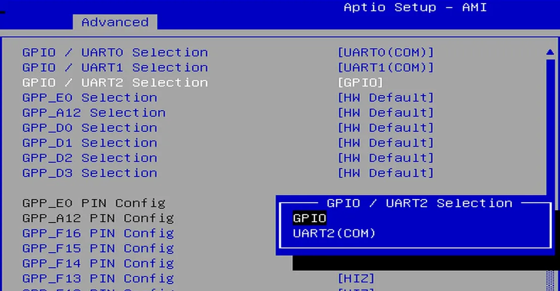
GPIO Configurationoption via the following path:Advanced -> GPIO Configuration. -
Configure the required pins to GPIO mode.
For example: If you do not need to use UART2 but wish to use the UART2 TXD and RXD pins as GPIOs, select "GPIO" as shown in the figure below.
-
Navigate to the
Save & Exit pageand selectSave Changes and Exitoption to save the BIOS settings and restart the LattePanda board.
GPIO Address
The mapping between the physical pins and the pin numbers (used in the code) is shown in the table below.
| Pin Name | PIN Mapping Number |
|---|---|
| GPP_A12 | 0 |
| GPP_E0 | 1 |
| GPP_D0 | 2 |
| GPP_D1 | 3 |
| GPP_D2 | 4 |
| GPP_D3 | 5 |
| GPP_F12 | 6 |
| GPP_F13 | 7 |
| GPP_F14 | 8 |
| GPP_F15 | 9 |
| GPP_F16 | 10 |
| SOC_UART0_RXD / GPP_H10 | 11 |
| SOC_UART0_TXD / GPP_H11 | 12 |
| SOC_UART1_RXD / GPP_D17 | 13 |
| SOC_UART1_TXD / GPP_D18 | 14 |
| SOC_UART2_RXD / GPP_F1 | 15 |
| SOC_UART2_TXD / GPP_F2 | 16 |
Programming with Python winsdk
Environment Setup
-
Intel serial IO controller drivers must be installed on the Windows OS.
It is recommended to install the Chipset driver and the SerialIO driver.
-
Download the Python installation package; versions 3.10, 3.11, or 3.12 are recommended.
- The winsdk dependencies required for I2C and GPIO do not support version 3.13 or higher. Therefore, versions 3.10, 3.11, or 3.12 are recommended.
- This tutorial uses version 3.11.9 Windows installer (64-bit).
-
Install dependencies
pip install winsdk
GPIO Output
The following code sets the GPP_F12 pin to output mode and toggles the output level signal every second.
- Save the following code as a Python file, for example,
gpio_toggle_demo.py.
import platform
import time
from datetime import datetime

# Define the target GPIO pin by its physical name (e.g., 'GPP_D0', 'GPP_F12', etc.)
TARGET_PIN_NAME = "GPP_F12"
INTERVAL_MS = 1000

# Mapping table: Physical GPIO Pin Name to WinRT Mapping Number
PIN_MAPPING = {
    "GPP_A12": 0,
    "GPP_E0": 1,
    "GPP_D0": 2,
    "GPP_D1": 3,
    "GPP_D2": 4,
    "GPP_D3": 5,
    "GPP_F12": 6,
    "GPP_F13": 7,
    "GPP_F14": 8,
    "GPP_F15": 9,
    "GPP_F16": 10,
    "GPP_H10": 11,    # SOC_UART0_RXD
    "GPP_H11": 12,    # SOC_UART0_TXD
    "GPP_D17": 13,    # SOC_UART1_RXD
    "GPP_D18": 14,    # SOC_UART1_TXD
    "GPP_F1": 15,    # SOC_UART2_RXD
    "GPP_F2": 16,    # SOC_UART2_TXD
}

# Resolve the target pin name to its mapping number
if TARGET_PIN_NAME not in PIN_MAPPING:
    raise SystemExit(f"Error: Pin name '{TARGET_PIN_NAME}' is not valid or supported.")
PIN = PIN_MAPPING[TARGET_PIN_NAME]

if platform.system().lower() != "windows":
    raise SystemExit("This script is for Windows only.")

try:
    from winsdk.windows.devices.gpio import GpioController, GpioPinDriveMode, GpioPinValue
except ImportError:
    raise SystemExit("Missing dependency: winsdk (pip install winsdk)")

# Initialize GPIO Controller
controller = GpioController.get_default()
if controller is None:
    raise SystemExit("WinRT GPIO controller is unavailable.")

# Open and configure the target pin
pin = controller.open_pin(PIN)
pin.set_drive_mode(GpioPinDriveMode.OUTPUT)
low = GpioPinValue.LOW
high = GpioPinValue.HIGH
pin.write(low)
state = low

print(f"Successfully initialized {TARGET_PIN_NAME} (Mapped to Pin {PIN})")

try:
    while True:
        # Toggle pin state
        state = high if state == low else low
        pin.write(state)
        text = "High" if state == high else "Low"
        print(f"{datetime.now():%H:%M:%S} {TARGET_PIN_NAME} -> {text}")
        time.sleep(INTERVAL_MS / 1000)
except KeyboardInterrupt:
    pass
finally:
  # ── Safe release sequence ─────────────────────────────────────────────────
    # Step 1: Drive pin LOW to discharge any residual state before releasing
    try:
        pin.write(low)
    except Exception:
        pass  # Ignore if pin is already in an error state

    # Step 2: Switch to INPUT (high-impedance) so the pin is no longer actively driven after release.
    if pin.is_change_drive_mode_supported(GpioPinDriveMode.INPUT):
        pin.set_drive_mode(GpioPinDriveMode.INPUT)
        print(f"{TARGET_PIN_NAME} released → INPUT (high-impedance)")
    else:
        print(
            f"Warning: {TARGET_PIN_NAME} does not support INPUT mode; "
            "closing pin handle directly."
        )

    # Step 3: Close the WinRT pin handle
    pin.close()
    print(f"{TARGET_PIN_NAME} handle closed.")
- Navigate to the directory containing the
gpio_toggle_demo.pyfile and run the following command in the terminal. You will observe theGPP_F12pin outputting high and low signals at approximately 1-second intervals.
python gpio_toggle_demo.py
GPIO Input
The following code sets the GPP_F12 pin to input mode and read its level status every 0.5 seconds.
import platform
import time
from datetime import datetime

# Define the target GPIO pin by its physical name(e.g., 'GPP_D0', 'GPP_F12', etc.)
TARGET_PIN_NAME = "GPP_F12"
INTERVAL_MS = 500

# Mapping table: Physical GPIO Pin Name to WinRT Mapping Number
PIN_MAPPING = {
    "GPP_A12": 0,
    "GPP_E0": 1,
    "GPP_D0": 2,
    "GPP_D1": 3,
    "GPP_D2": 4,
    "GPP_D3": 5,
    "GPP_F12": 6,
    "GPP_F13": 7,
    "GPP_F14": 8,
    "GPP_F15": 9,
    "GPP_F16": 10,
    "GPP_H10": 11,    # SOC_UART0_RXD
    "GPP_H11": 12,    # SOC_UART0_TXD
    "GPP_D17": 13,    # SOC_UART1_RXD
    "GPP_D18": 14,    # SOC_UART1_TXD
    "GPP_F1": 15,     # SOC_UART2_RXD
    "GPP_F2": 16,     # SOC_UART2_TXD
}

INTERVAL_MS = 500

if platform.system().lower() != "windows":
    raise SystemExit("This script is for Windows only.")

try:
    from winsdk.windows.devices.gpio import GpioController, GpioPinDriveMode, GpioPinValue
except ImportError:
    raise SystemExit("Missing dependency: winsdk (pip install winsdk)")

if TARGET_PIN_NAME not in PIN_MAPPING:
    raise SystemExit(f"Invalid pin name: '{TARGET_PIN_NAME}'. Please choose a valid pin.")

PIN = PIN_MAPPING[TARGET_PIN_NAME]

controller = GpioController.get_default()
if controller is None:
    raise SystemExit("WinRT GPIO controller is unavailable.")

pin = controller.open_pin(PIN)
# Configure the pin as input to read external levels
pin.set_drive_mode(GpioPinDriveMode.INPUT)
high = GpioPinValue.HIGH

try:
    while True:
        # Read the current digital level of the pin
        value = pin.read()
        level = "High" if value == high else "Low"
        print(f"{datetime.now():%H:%M:%S} Pin {TARGET_PIN_NAME} = {level}")
        time.sleep(INTERVAL_MS / 1000)
except KeyboardInterrupt:
    pass
finally:
    # Release the pin resource on exit
    pin.close()